Two-part linkage assembly – 3D CAD Exercise 180
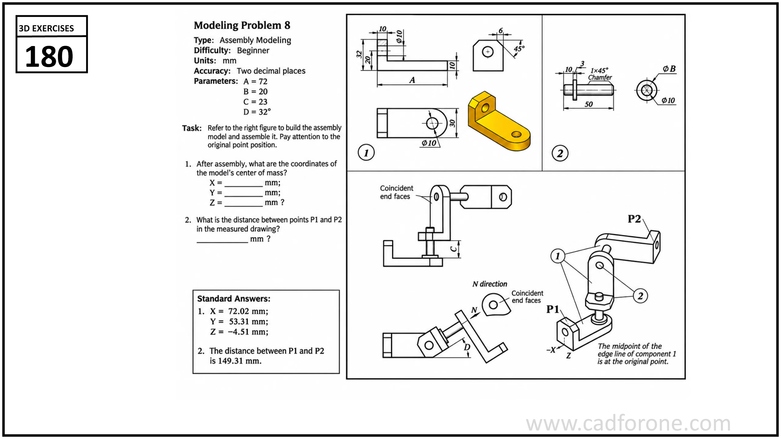
A two-part linkage assembly with a pin, a bent bracket, and specified relative positioning.
Drawing reading checks
- Model the two parts independently, then apply the shown coincident and angular relationships.
- Set the assembly origin before checking center of mass and the distance between the marked points.
Check your result
- Keep the components separate and compare their relative positions with the assembly view. Check the listed parts before treating the assembly as complete.